| Geometry of the view projection | ||
|---|---|---|
 | ||
|
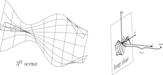
The relation between the 3d scene and the 2d image plane where the 3d scene is projected by ..Shapes..Geometry3D..view. The source is not meant to be instructive.
| ||
| Source: show/hide — visit | ||
##needs ..Shapes..Data / seq-support
##needs ..Shapes..Graphics / braces
##needs ..Shapes..Graphics3D / metapostarrow
##needs ..Applications..Blockdraw

##lookin ..Shapes
##lookin ..Shapes..Geometry3D
##lookin ..Shapes..Graphics3D
##lookin ..Applications..Blockdraw

dir: Geometry..dir
normalized: Geometry..normalized

R: 5cm
u: R/2.1

/** The function describing the manifold.
 **/
surfz: \ p → (0.24*R) * [Numeric..Math..sin (p.x/u) * (p.y/u)]

/** A general-purpose helper.
 **/
surfit: \ f p → ( p.x, p.y, [f p] )

/** A general-purpose surface-circle.
 **/
surfaceCircle: \ f r c sides:'12 →
{
  mid: [surfit f c]
  [[Data..range '0 sides-'1].foldl
   \ p e → p & [Graphics..fill mid--[surfit f c+r*[dir (360°*e)/sides]]--[surfit f c+r*[dir (360°*(e+'1))/sides]]--cycle]
   null]
}


foldpairsl:
{
  helper: \ op zero last lst → [if [Data..nil? lst] zero [helper op [op zero last lst.car] lst.car lst.cdr]]

  \ op zero lst →
    [if [Data..nil? lst]
      lst
      [helper op zero lst.car lst.cdr]]
}

foldtriplesl:
{
  helper: \ op zero back2 back1 lst → [if [Data..nil? lst] zero [helper op [op zero back2 back1 lst.car] back1 lst.car lst.cdr]]

  \ op zero lst →
    [if [Data..nil? lst]
      lst
      [if [Data..nil? lst.cdr]
        Data..nil
        [helper op zero lst.car lst.cdr.car lst.cdr.cdr]]]
}

functionMesh: \ zMap xRange yRange step:'1 →
{
  xyz: \ p → ( p.x, p.y, [zMap p] )
  [[Data..downsample xRange step].foldl
    \ p x →
      p
      &
      [Graphics..stroke
        [yRange.foldl
           \ p y → p--[xyz (x,y)]
           Geometry3D..emptypath
      ]]
    null]
  &
  [[Data..downsample yRange step].foldl
    \ p y →
      p
      &
      [Graphics..stroke
        [xRange.foldl
           \ p x → p--[xyz (x,y)]
           Geometry3D..emptypath
      ]]
    null]
}

functionSurface: \ zMap xRange yRange →
{
  xyz: \ p → ( p.x, p.y, [zMap p] )
  [foldpairsl
    \ p x1 x2 →
      p
      &
      [foldpairsl
         \ p y1 y2 →
          p
          &
          {
            p11: [xyz (x1,y1)]
            p12: [xyz (x1,y2)]
            p21: [xyz (x2,y1)]
            p22: [xyz (x2,y2)]
            pc: [xyz (0.5*(x1+x2),0.5*(y1+y2))]
            [Graphics..fill pc--p11--p12--cycle]
            &
            [Graphics..fill pc--p12--p22--cycle]
            &
            [Graphics..fill pc--p22--p21--cycle]
            &
            [Graphics..fill pc--p21--p11--cycle]
          }
         null
        yRange
      ]
    null
    xRange
  ]
/**
  &
  [functionMesh zMap xRange yRange]
**/
}

ridgeLines:
{
  ridgeTest: \ p1 p2 o1 o2 →
  {
    d11: [normalized o1 - p1]
    d12: [normalized o2 - p1]
    dm1: d11 + d12
    d21: [normalized o1 - p2]
    d22: [normalized o2 - p2]
    dm2: d21 + d22
    dc: [normalized p2 - p1]
    ( dm1*dc ≤ dm1*d11 ) and ( ~(dm2*dc) ≤ dm2*d22 )
  }

 \ zMap xRange yRange tf →
  {
    xyz: \ p → ( p.x, p.y, [zMap p] )

    [foldpairsl
      \ p x1 x2 →
        [foldpairsl
          \ p y1 y2 →
            {
              p11: [xyz (x1,y1)] >> tf >> view
              p12: [xyz (x1,y2)] >> tf >> view
              p21: [xyz (x2,y1)] >> tf >> view
              p22: [xyz (x2,y2)] >> tf >> view

              pc:  [xyz (0.5*(x1+x2),0.5*(y1+y2))] >> tf >> view
              pc3D: [xyz (0.5*(x1+x2),0.5*(y1+y2))]

              p
              &
                  [if [ridgeTest p11 pc p12 p21] [Graphics..stroke [xyz (x1,y1)]--pc3D] null]
                  &
                  [if [ridgeTest p12 pc p11 p22] [Graphics..stroke [xyz (x1,y2)]--pc3D] null]
                  &
                  [if [ridgeTest p22 pc p12 p21] [Graphics..stroke [xyz (x2,y2)]--pc3D] null]
                  &
                  [if [ridgeTest p21 pc p11 p22] [Graphics..stroke [xyz (x2,y1)]--pc3D] null]
            }
          p
          yRange
        ]
      null
      xRange
    ]
    &
    [foldtriplesl
      \ p x1 x2 x3 →
        [foldpairsl
          \ p y1 y2 →
            {
              p1: [xyz (x2,y1)] >> tf >> view
              p2: [xyz (x2,y2)] >> tf >> view
              pc1: [xyz (0.5*(x1+x2),0.5*(y1+y2))] >> tf >> view
              pc2: [xyz (0.5*(x2+x3),0.5*(y1+y2))] >> tf >> view
              [if [ridgeTest p1 p2 pc1 pc2]
                p & [Graphics..stroke [xyz (x2,y1)]--[xyz (x2,y2)]]
                p]
            }
          p
          yRange
        ]
      null
      xRange
    ]
    &
    [foldtriplesl
      \ p y1 y2 y3 →
        [foldpairsl
          \ p x1 x2 →
            {
              p1: [xyz (x1,y2)] >> tf >> view
              p2: [xyz (x2,y2)] >> tf >> view
              pc1: [xyz (0.5*(x1+x2),0.5*(y1+y2))] >> tf >> view
              pc2: [xyz (0.5*(x1+x2),0.5*(y2+y3))] >> tf >> view
              [if [ridgeTest p1 p2 pc1 pc2]
                p & [Graphics..stroke [xyz (x1,y2)]--[xyz (x2,y2)]]
                p]
            }
          p
          xRange
        ]
      null
      yRange
    ]
  }
}

T_obj: [shift (0cm,0cm,~10cm)]*[Geometry3D..rotate dir:(1,0,0) angle:~90°-~19°]*[Geometry3D..rotate dir:(0,0,1) angle:~90°+25°]

N_major: '8
N_minor: '2
xRange: [Data..range ~R R count: N_major * N_minor + '1]
yRange: [Data..range ~R R count: N_major * N_minor + '1]

world:
(
@eyez:5cm
|
{

•imagePlane: Graphics..newGroup
•imagePlane
      << Traits..@width:0.8bp
         |
         [view
           T_obj
           []
           ( newZSorter
             <<   Traits..@nonstroking:Traits..BW..OCCLUDING
                  | [functionSurface surfz xRange yRange]
             << [functionMesh surfz xRange yRange N_minor]
             << [ridgeLines surfz xRange yRange T_obj]
           )
         ]

•imagePlane << Traits..@width:0.3bp | [Graphics..stroke [Geometry..rectangle (~3cm,~3cm) (3cm,3cm)]]
            << [Geometry..shift (~3cm,~3cm)+(5mm,5mm)] [] [Graphics..TeX `{\Huge Image plane}´]

•world: newGroup
len: 4cm
•world << [immerse (•imagePlane)]
     << [Graphics..stroke (0cm,0cm,0cm)--(len,0cm,0cm) head:[MetaPostArrow ahLength:3mm normal:(0,0,1) ...]]
     << [Graphics..stroke (0cm,0cm,0cm)--(0cm,len,0cm) head:[MetaPostArrow ahLength:3mm normal:(0,0,1) ...]]
     << [Graphics..stroke (0cm,0cm,0cm)--(0cm,0cm,len) head:[MetaPostArrow ahLength:3mm normal:(1,0,0) ...]]
     << [shift (len,0cm,0cm)] [] [facing [putlabelAbove [Graphics..TeX `$\hat{x}$´] (0cm,0cm) 1]]
     << [shift (0cm,len,0cm)] [] [facing [putlabelRight [Graphics..TeX `$\hat{y}$´] (0cm,0cm) 1]]
     << [shift (0cm,0cm,len)] [] [facing [putlabelAbove [Graphics..TeX `$\hat{z}$´] (0cm,0cm) 1]]
     << [shift (0cm,0cm,@eyez)] [] [facing [Graphics..fill [Geometry..circle 2bp]]]
     << [shift (0cm,0cm,@eyez)] [] [facing [putlabelAbove [Graphics..TeX `eye´] (0cm,1mm) 0]]
     << [Graphics..Tag..tag 'eye (0cm,0cm,@eyez)]
     << [Graphics..Tag..tag 'origin (0cm,0cm,0cm)]

  bracePath: [Geometry3D..rotate dir:(0,1,0) angle:~90°] [] [immerse [Graphics..someClosedBrace (0cm,0cm) (@eyez,0cm)]]
  •world << [Graphics..fill bracePath]
  |** Next, I use that I happen to know that the tip of the brace is at path time 1.
  •world << [shift [bracePath 1].p] [] [facing [putlabelBelow [Graphics..TeX `$z_{\mathrm{eye}}$´] (0m,0m) 0]]

freeze •world
}
)

T_view: [shift (0cm,~40cm,0cm)]*[Geometry3D..rotate dir:(0,1,0) angle:65°]*[Geometry3D..rotate dir:(0,0,1) angle:15°]*[Geometry3D..rotate dir:(1,0,0) angle:5°]

@eyez:∞
|
{

theView:
Traits..@width:0.3bp
|
[view
  (T_view * T_obj)
  []
  ( newZSorter
|**            << Traits..@nonstroking:Traits..BW..OCCLUDING | [functionSurface surfz xRange yRange]
    << [functionMesh surfz xRange yRange N_minor]
    << [ridgeLines surfz xRange yRange T_view * T_obj]
  )
]

IO..•page << theView
      << [view (T_view * T_obj) [] [facing [putlabelBelow [Graphics..TeX `{\huge $3^{\mathrm{D}}$ scene}´] (~2cm,~3cm) 0]]]
      << [view T_view [] world]
}
| ||

